Design of Protective Pipes for Steam Pipes in Chemical Process Units (Part Two)
2.2 Designing drainage facilities
In order to ensure the normal operation of the steam pipeline, it is required to establish drainage facilities in the system. For example, there is superheated steam in a 1000kt/a ethylene unit. According to the pipeline conditions during the operation of the device and the characteristics of the steam, separate drainage may no longer be needed.
The condensate produced during the operation of ultra high-pressure steam 13MPa is little and can be ignored. It can be discharged directly through the drainage facility at low positions. The water conveying facilities are not necessary to be provided. The shut-off valve, root valve, and exhaust tube constitute the drainage facility. Low-pressure steam 0.4MPa, medium-pressure steam 1.6MPa, and high-pressure steam systems 4MPa have less condensate during normal operation, but a lot of condensates will appear at a heating state. Therefore, drainage facilities should be set according to different pressure. Steam traps, liquid distribution bags, root valves, and check valves are the main components for water conveying facilities, as shown in Figure 1.
2.3 Designing branches of steam pipes
The status of the system radiator is one of the important factors that need to be considered during the inspection of branches of steam pipes. It is required to design the corresponding branches of steam pipes, combined specific furnace usage and operation requirements of pipelines. Flexibly choose the best installation method for radiators. Meanwhile, the installation slope of the branch pipe should be effectively designed to install the radiator more firmly and reliably. In the design process, it is required to combine the different grades of the steam pipeline operation and arrange the regular drainage facilities and drainage facilities at the low position of the branch of steam pipes. In the layout process, the installation position generally adopts the lowest point of the control valve, branch of steam pipes, the low point before pressure reducing valves and shut-off valves of inlet pipes, water separators of conveying process systems, before shut-off valves of inlet steam pipes, heating instrument, bottoms of the expansion vessel and distribution pipe.
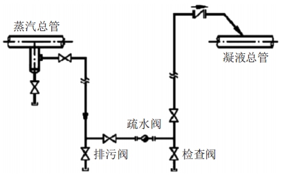
Figure 1 The structure diagram of main pipelines of high-pressure steam
2.4 Designing steam condensate pipes
Generally, steam condensate pipes are set in the unified level of steam pipes. In the design process, it is also necessary to design and install "II" compensators for them. In the installation process, attention should be paid to avoiding the impact of the water hammer on the equipment. Under the changed circumstances, certain hidden dangers are brought to the operation of the system. Therefore, the design should be performed in the horizontal direction, or design the "II" shape compensator standpipe according to the inclined direction to avoid the water hammer during the operation of the system.
During the operation of the system, steam with different pressure has corresponding condensate pipes. After passing through the steam trap, the condensate is connected through the flange. In the steam pipe, there are some branch pipes whose diameters are less than or equal to 50mm. The medium can be discharged to recycled pipes in the upward direction of 45 degrees. If the branch pipe is less than 50mm, the medium will be discharged to recycled pipes in the upward direction of 90 degrees. The main valve for recycling condensate generally adopts the horizontal direction in the process of designing the check valve.
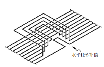
Figure 2 The design of "II" shape compensator in the horizontal direction
3. Conclusion
Condensate pipelines have the characteristics of vapor liquid two-phase flow in the operation process, and they have high temperatures during transportation. Therefore, it is required to optimize the design of the pipeline. The protective piping design should meet the allowable range of the operation of each stress supporting point in the process of system operation. Corresponding design is carried out in accordance with the pipe's frame structure to promote the safe and normal operation of protective piping and enhance the safety of system operation.
In order to ensure the normal operation of the steam pipeline, it is required to establish drainage facilities in the system. For example, there is superheated steam in a 1000kt/a ethylene unit. According to the pipeline conditions during the operation of the device and the characteristics of the steam, separate drainage may no longer be needed.
The condensate produced during the operation of ultra high-pressure steam 13MPa is little and can be ignored. It can be discharged directly through the drainage facility at low positions. The water conveying facilities are not necessary to be provided. The shut-off valve, root valve, and exhaust tube constitute the drainage facility. Low-pressure steam 0.4MPa, medium-pressure steam 1.6MPa, and high-pressure steam systems 4MPa have less condensate during normal operation, but a lot of condensates will appear at a heating state. Therefore, drainage facilities should be set according to different pressure. Steam traps, liquid distribution bags, root valves, and check valves are the main components for water conveying facilities, as shown in Figure 1.
2.3 Designing branches of steam pipes
The status of the system radiator is one of the important factors that need to be considered during the inspection of branches of steam pipes. It is required to design the corresponding branches of steam pipes, combined specific furnace usage and operation requirements of pipelines. Flexibly choose the best installation method for radiators. Meanwhile, the installation slope of the branch pipe should be effectively designed to install the radiator more firmly and reliably. In the design process, it is required to combine the different grades of the steam pipeline operation and arrange the regular drainage facilities and drainage facilities at the low position of the branch of steam pipes. In the layout process, the installation position generally adopts the lowest point of the control valve, branch of steam pipes, the low point before pressure reducing valves and shut-off valves of inlet pipes, water separators of conveying process systems, before shut-off valves of inlet steam pipes, heating instrument, bottoms of the expansion vessel and distribution pipe.
Figure 1 The structure diagram of main pipelines of high-pressure steam
2.4 Designing steam condensate pipes
Generally, steam condensate pipes are set in the unified level of steam pipes. In the design process, it is also necessary to design and install "II" compensators for them. In the installation process, attention should be paid to avoiding the impact of the water hammer on the equipment. Under the changed circumstances, certain hidden dangers are brought to the operation of the system. Therefore, the design should be performed in the horizontal direction, or design the "II" shape compensator standpipe according to the inclined direction to avoid the water hammer during the operation of the system.
During the operation of the system, steam with different pressure has corresponding condensate pipes. After passing through the steam trap, the condensate is connected through the flange. In the steam pipe, there are some branch pipes whose diameters are less than or equal to 50mm. The medium can be discharged to recycled pipes in the upward direction of 45 degrees. If the branch pipe is less than 50mm, the medium will be discharged to recycled pipes in the upward direction of 90 degrees. The main valve for recycling condensate generally adopts the horizontal direction in the process of designing the check valve.
Figure 2 The design of "II" shape compensator in the horizontal direction
3. Conclusion
Condensate pipelines have the characteristics of vapor liquid two-phase flow in the operation process, and they have high temperatures during transportation. Therefore, it is required to optimize the design of the pipeline. The protective piping design should meet the allowable range of the operation of each stress supporting point in the process of system operation. Corresponding design is carried out in accordance with the pipe's frame structure to promote the safe and normal operation of protective piping and enhance the safety of system operation.