Test Methods for Fully Automatic Argon Arc Welding of Carbon Steel Pipes
At present, the welding of carbon steel pipes with small diameters mainly adopts manual argon arc welding processes. In engineering projects, such pipelines have the characteristics of small diameters, thin wall, but large quantities. Therefore, there is still much room for improvement in welding production efficiency, welding quality and manpower input. Given this situation, we intend to develop a fully automatic welding process for small-diameter carbon steel pipelines with high welding production efficiency and high welding qualification rate.
For the welding operation of the 4-inch pipelines with much workload on site, the imported small-diameter carbon steel pipeline automatic welding equipment is used to develop the corresponding welding process, and obtain matching equipment, welding consumables, welding processes, welding operation methods, welder training and other welding technology solutions, provide technical support for engineering project application and subsequent development.
Test methods for fully automatic argon arc welding of carbon steel pipes
1.1 Test materials and equipment
The test base material in this subject is A106 Gr.B. The process pipeline has a specification of 114.3 mm × 13.49 mm, and it is normalized. Welding consumables should be selected according to the specified performance requirements of the welded joint and welding equipment. By comparison, the welding material for automatic argon arc welding adopts the JM-56 (SFA/AWS A5.18: ER70S-6) welding wire of Lincoln Electric Company. The chemical composition and mechanical properties of base metal and welding consumables are shown in Table 1 and Table 2.
Table 1 Main chemical composition (mass fraction) of base metal and welding consumables (%)
| Materials | C | Mn | Si | P | S | Ni | Cr | Mo | Cu | V |
| A 106Gr.B | 0.21 | 0.49 | 0.23 | 0.013 | 0.011 | 0.08 | 0.07 | 0.01 | 0.08 | 0.01 |
| JM-56 | 0.071 | 1.44 | 0.80 | 0.012 | 0.015 | 0.007 | 0.03 | 0.001 | 0.14 | 0.003 |
Table 2 Mechanical properties of base metal and welding consumables
| Materials | Tensile tests | Impact tests | |||
| Rel/MPa | Rm/MPa | A(%) | Temperature/℃ | A kv/J | |
| A 106Gr.B | 280 | 480 | 27 | 0 | 75, 64 and 62 |
| JM-56 | 500 | 590 | 26 | -30 | 102, 94 and 90 |
The welding test adopts fully automatic argon arc welding equipment in all positions, which is suitable for the welding of carbon steel, stainless steel, and small diameter pipes.
1.2 Forms of welded joints
The groove form is shown in Figure 1.
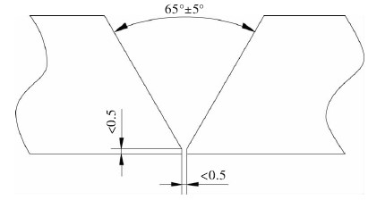
Figure 1 The schematic diagram of welding grooves
1.3 Process parameters
The welding position is 5G. The welding area should be cleaned before welding, and then preheated to 20℃. The shielding gas used in gas tungsten arc welding (GTAW) is φ(Ar) 99.99% argon. In order to ensure high-quality welded joints, each layer of welding seam is thoroughly cleaned after welding, and the next layer of welding seam is welded after grinding. The specific welding sequence is shown in Figure 2.
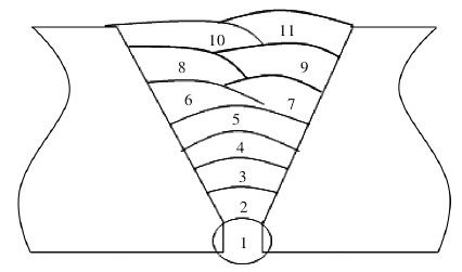
Figure 2 The schematic diagram of the welding sequence
After theoretical analysis and actual test welding, the welding process parameters were continuously adjusted to adjust the heat input during welding. Combined with the mechanical properties test analysis of the welded joint, after many tests, the optimized welding process parameters under the test conditions were finally determined as shown in Table 3.
Table 3 Welding process parameters of air arc welding
| Welding layers | Power polarity | Welding current/A | Arc voltage/V | Welding speeds cm.mini-1) | Gas flow/ (L.min-1) |
| The bottom layer | DC(+) | 170 | 9.4 | 8 | 20 to 25 |
| The filling layer | DC(+) | 120 to 160 | 8.6 | 6 to 7 | 20 to 25 |
| The cover layer | DC(+) | 140 | 8.6 | 4-5 | 20 to 25 |